
X-ray fluorescence (XRF) can be used to detect a material’s chemical composition. It is based on measuring the fluorescence of individual atoms. This fluorescence effect is created by shooting a beam of high energy x-rays on a material. XRF is a well-established analysis technique that is used by many laboratories around the world. For analysing ores and rocks, laboratory XRF instruments require a sample preparation by producing a pressed tablet or glass bead from a pulverised and homogenised sample. If the sampling and sample preparation is carried out well, this provides low detection limits and highly accurate results.
The laboratory type of XRF analysers cannot be used for real-time measurements on a conveyor belt or in the field. Real-time XRF is based on the same physical principles, but performs the task without any sample preparation. The performance in terms of detection limit and accuracy is therefore usually lower, which is an important difference that is sometimes overlooked. Calibration of real-time XRF analysers is also more difficult since mineral heterogeneity, matrix effects, and analyser spot size need to be taken into account. Real-time XRF sensors are still very useful tools when this calibration is carried out well. It is used in many kinds of applications including handheld analysers, drill core scanning systems, conveyor belt analysers, particle-by-particle sorting machines, and truck/excavator load scanning.
Working principle
The term fluorescence generally refers to the absorption of light by a material that is followed by an immediate emission. The emitted light often has a lower energy (longer wavelength) than the light that was absorbed. The fluorescence effect is produced by a change of the energy state of an atom or molecule. A higher energy state is reached by absorbing the light, which is not stable and results in energy release through light emission.
In XRF, a beam of high-energy x-rays are shot on a material which causes electrons that are orbiting the core of an atom to absorb these rays and gain energy. The energy gain causes them to lose orbit, which leaves an energy hole at this orbit. This energy hole is immediate filled by one of the other electrons that are orbiting the atom and the energy release associated with this produces emissions of x-rays1.
The amount of energy that is released depends on the type of atom around which the hole was created. This means that the different elements in the material all produce emissions at different wavelengths. Chemical composition is determined by recording the intensity of the different x-ray emissions and using some kind of calibration to convert the x-ray spectrum to element concentrations. The figure below shows an example of an XRF spectrum.
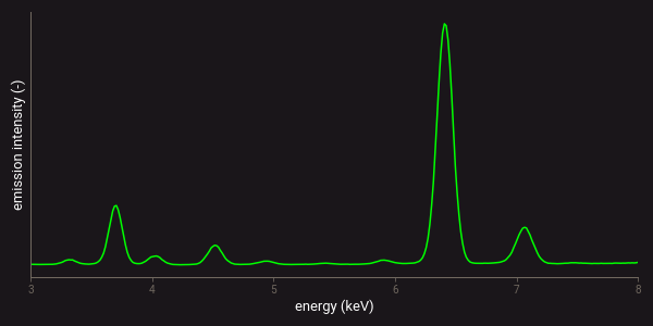
Example of an XRF spectrum.
X-ray tubes are commonly used in XRF as a source of the x-rays. Alternatively, a radioactive material can be used as a source. This has the advantage that replacement of the source is needed less frequently, which is especially convenient for industrial applications. The disadvantage is the radiation hazard that is associated with nuclear sources.
X-ray fluorescence (XRF) is different than laser-induced fluorescence (LIF) and x-ray luminescence (XRL). The LIF and XRL techniques are also based on the fluorescence effect, but the emissions are measured in the visible and near-infrared ranges of the electromagnetic spectrum. These emissions also result from lower-energy processes such as electron transitions in molecules. The LIF and XRL techniques can be used to detect the occurrence of minerals, while XRF detects the concentration of chemical elements in a material.
Light elements are difficult to detect with XRF because the energy of the radiation that is emitted by these elements is low and has a low penetrating power1. As a result, these emissions are more quickly absorbed by other elements and the surrounding air. This problem can be overcome by measuring in an environment where the air is replaced by helium. However, in industrial applications such a setup is often not feasible. Furthermore, a special configuration of the XRF sensor is needed to detect elements that are lighter than sodium. Hydrogen, helium and lithium cannot be detected with XRF at all.
General characteristics
XRF spectroscopy is a surface technique. Only point spectrometers are available to measure XRF spectra. Collecting a single spectrum with such an instrument typically takes around 30 seconds. The measurement time depends on the required accuracy and precision of the measurement and on the concentration range of the elements of interest. For conveyor belt scanning a moving average is usually collected that represents all material that passes the sensor within the 30 s. measurement window. The same approach is applied in some drill core scanning applications.
Hyperspectral images can be collected by measuring XRF spectra point-by-point over a raster. This is often a time consuming process due to the relatively long measurement time. It is also possible to use an XRF line scan system to simultaneously collect spectra at different spots across the width of a conveyor belt. These systems consist of multiple point spectrometers that are placed in a row. Such line scan systems are therefore different from the ones used in reflectance spectroscopy, where the different spots or pixels of the line scan are acquired with a single detector.
The measurement time of XRF analysers can be significantly reduced by restricting the spectral range that is measured. This means that also the number of chemical elements that are detected is reduced. This approach is used in particle-by-particle sorting machines that are based on XRF detection. By detecting only one or several elements simultaneously, scanning speeds up to 100 Hz are possible. The maximum speed does depend on the concentration range of the elements of interest and the required accuracy and precision of the analysis.
Contrast
Individual elements produce multiple emission lines or peaks that often have little overlap with other elements. There are some common interferences though, which include arsenic (As) and lead (Pb), iron (Fe) and chromium (Cr), and titanium (Ti) and barium (Ba).
The energy of the major XRF emission lines is sometimes indicated on a periodic table of elements (denoted by kα and lα). Several databases with a full list of element emissions are also available. An example is the NIST x-ray transition energies database. Any potential overlap of element emissions can be investigated with this database.
Detection limits
Detection limits of XRF are relatively low for most elements, typically reaching down to several tens of ppm. Apart from the physical process producing x-ray emissions, detection limits also depend on the hardware configuration of the sensor. This means that in some cases multiple XRF analysers may be required to reach the required detection limits for all elements of interest.
Several manufacturers of handheld XRF analysers have published lists of the detection limits for their instruments. It should be noted that little to no information is usually available on how these detection limits were determined. In order to assess the applicability of an XRF sensor for a specific ore type, it is therefore advised to perform some test measurements to check if the elements of interest can be detected.
Matrix effects
The influence of matrix effects in XRF is relatively high. This is mainly because the radiation that is emitted by a specific element can be re-absorbed by other elements in the sample. The amount of re-absorption strongly depends on the composition of the material that is measured. Additionally, re-absorbed x-rays may enhance the fluorescence of other elements1.
Because of the matrix effects, XRF instrument calibrations that convert measured emissions to element concentration are only valid for a certain range of compositions. This often means that re-calibration is required before an XRF analyser can be used to measure the composition of a certain ore type. Such a re-calibration should be based on samples from the same deposit as where the analyser is used.
Safety
XRF sensors use an x-ray source that produces hazardous radiation. However, the sensor generally needs to be in very close contact with the material to minimise x-ray absorption by air and maximise performance. This mitigates the radiation hazard somewhat as little to no gap is present through which the x-rays can escape. Safe operation of handheld XRF analysers is therefore possible as long as the analyser is always pressed against a sample when the measurement is performed. However, in applications such as conveyor belt scanning or particle-by-particle sorting some sort of shielding of the analyser is usually needed to prevent hazardous x-rays from escaping to the environment.
Further reading
The related books section of the RockDataAcademy provides several references to books with detailed descriptions of XRF spectroscopy and its applications. The chapter “Introduction to XRF” within the open-access library of Libretexts chemistry also provides a good introduction to XRF spectroscopy that can be accessed for free. Additionally, the wikipedia article “X-ray fluorescence” provides useful descriptions of the underlying physics and applications of the technology.
A scientific paper that is worth mentioning is “A review of the handheld X-ray fluorescence spectrometer as a tool for field geologic investigations on earth and in planetary surface exploration” by Young et al. (2016, Applied Geochemistry). This paper provides an excellent review of the handheld XRF technology for measuring geologic samples. It highlights the need for calibration and shows that good accuracy and precision of handheld XRF analysers can be obtained if proper calibration of the analyser is performed.
References
- Beckhoff, B., Kanngießer, B., Langhoff, N., Wedell, R. & Wolff, H. Handbook of Practical X-Ray Fluorescence Analysis. (Springer Science & Business Media, 2007).